
Gapechkin Anton
Faculty Computer Science and Technology
Speciality Computer Systems and Networks
Theme of master's work
An analysis of behavior of movable object is in the reserved space
Scientific adviser: Malcheva Raisa
Scientific assistant: Krivosheev Sergey
Resume
Abstract
Сontent
Topicality
The scientific importance of
The practical value of the work
Dynamic positioning
Management systems
Mathematical model
Optimal assessment
Methods for determining the coordinates of the object
Conclusion
Remark
References
Introduction
Theme of master's work
An analysis of behavior of movable object is in the reserved space
Scientific adviser: Malcheva Raisa
Scientific assistant: Krivosheev Sergey
Abstract
Сontent
Topicality
The scientific importance of
The practical value of the work
Dynamic positioning
Management systems
Mathematical model
Optimal assessment
Methods for determining the coordinates of the object
Conclusion
Remark
References
Introduction
Modern technological advances in information technology significantly expands the tactical and technical capabilities of mobile
different objects. Significant role in this process is problem solving orientation and navigation facilities at a new qualitative level. systems
solving these problems on board, come together in information and control systems of orientation and navigation (KOH). Along with the optimization of the control section
KOH, the general direction of development in recent decades is the significant increase in the accuracy and reliability of the information parameters of the recognized
orientation and navigation, ie improving the information of KOH. These circumstances largely determine the growth of the efficacy and safety
operation of moving objects[1].
The need to create KOH as complexes in which the outcome is largely achieved through the redundancy of information, optimization
its processing, optimizing the control part, due to the fact that only constructive and technological solutions to problems of orientation and navigation in the modern
level requirements, often lead to extraordinary expenses, and the pace of their implementation is much lower required rate of increase of information provision. In
However, another fundamental fact in the development of KOH is the shift to resource-saving technologies, which allows a significant gain in
weight and size characteristics of the equipment, reduce its cost, power consumption and improve reliability. Then one of the main ways
solutions - the miniaturization of sensors with respect to inertial systems is most clearly reflected in the transition, where appropriate, to
micromechanical inertial sensor. At the same time improved and advanced technology makrodatchikov KOH, particularly inertial
sensors and gauges graviinertsialnih.
In most cases, the core information of current and future KOH is infinite platform navigation system, satellite komplektiruemaya
navigation system. This approach is most fully manifested in particular in the aviation CON application design experience which is widely used
in the monograph.
Topicality
The task of calculating the coordinates of a moving object is relevant, because currently require high accuracy and reliability of object. In connection with this research is being conducted to improve the navigation systems and displays them on a higher level.
The scientific importance of
The scientific importance of this work is to develop a more accurate method of determining the coordinates of a moving object and hold it in a certain space.
The practical value of the work
In carrying out the work after the simulation with improved methods assume a more optimal and reliable
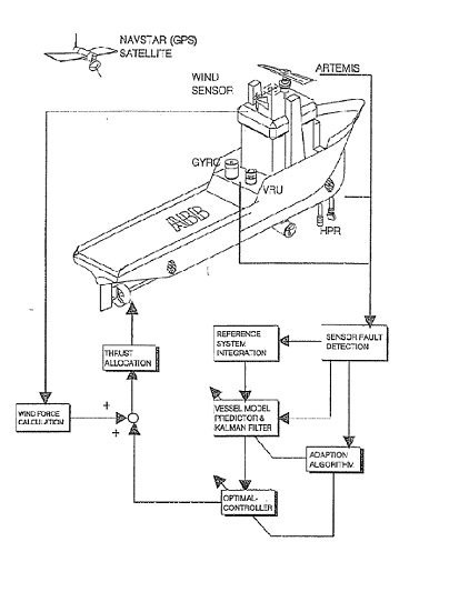
method of determining the origin and hold the object in a confined space. Generalized structure of KOH in the form of five inter-related functional
modules (Figure 1):
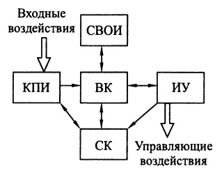
The table structure of the information base is KOH complex systems, the primary information sources (PIS), which measure different motion parameters and object state and transmit this information in analog or digital form in the computer system (CS). Figure 1 is designated: MEDI - means of entering and displaying information. CS - controls the subsystems of KOH and a managed object. IU - executive management device.
Dynamic positioning
Dynamic positioning systems have opened new opportunities for rapid development of marine research that
make the necessary scientific basis for all uses and development of the oceans.
Depending on the depth of the work now is mainly used in two ways to keep vessels in a given position: static system
positioning (anchoring restraint systems) and dynamic positioning systems.
Court, having high mobility is vital for the performance of work for exploration of oil and gas, large areas of the seas, when
requires frequent changes in the work area. At depths exceeding 200 m in the courts tend to use dynamic positioning system, providing
fairly quick and simple setting for a given point, the possibility of leaving the position with a deterioration in meteorological conditions and high accuracy
keeping the ship in place. Dynamic positioning can be performed automatically, semi-automatically or manually by operator commands to
remote control system of dynamic positioning. Abroad, the leading position on the development of dynamic positioning systems occupy
Norway and France. The first such system was created by the French firm and established in 1964 on the research vessel "Terebel". In the U.S., the development of
dynamic positioning systems company engaged in "Honeywell". The system of this company was first established on the drilling vessel "Glomar Challenger",
built in 1968 Experience in the operation of these systems on ships "Terebel" and "Glomar Challenger" proved their effectiveness. Court held in
given point during the action of wind and currents up to 3-6% of depth[2,3].
"Eureka" was the world's first computer-controlled dynamic positioning vessel. It was a semi-submersible, built the oil company "Shell"
for exploratory drilling and began its work in spring 1961. With one engine power for each of its 400 tons displacement, it was very successful
to take cores up to 150 meters into the seabed. Averaging over two points in the day, it was drilled to nine in one day at a depth of up to 1200 metrs.
Since this is the first operation of the dynamic positioning system, they have come a long way to go. Older analog (single stream system) and then went
digital computers are available in two, and then triple redundancy. Failure rates have gone from several a month and more than 20 percent
downtime in the first year, to date, the mean time between failure (MTBF) for about three years for better systems.
The development of successful dynamic positioning systems requires tools to verify the performance of the entire system of control for the reaction vessel
environment and forces the engine to the chassis. Complete simulation will give the system performance by means of mathematical analysis before any
equipment has been purchased. Then, using a detailed simulator of the system, you can modify the control system, hardware specifications,
screw design or even construction of the case, to get those necessary or effective in a changing environment, as well as in response to a sudden failure of
component of the system.
Management systems
Dynamic positioning systems, in general, it is the vessel's position relative to the target position and directs the force of various
motors, to correct any errors position. Without any modulation of the rod and providing a "dead zone", the system will be continuously
pereregulirovatsya. Perhaps the simplest practical system consists of a thrust and torque command proportional (P) in the amount and location of
direction of the error:
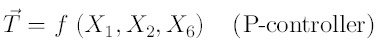
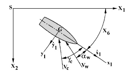
Chart axes system is shown in Figure 2, with the origin, S, from the Earth's axis in the system is still water surface.
Mathematical model
For dynamic positioning, floating of structures not only horizontal movements of low frequency waves (K = 1), the effect (K = 2)
and yaw (K = 6) are of interest. Engine power must balance and make waves, current and wind loads. In addition, xЎ and Xf, is
slowly varying structures. Remained high motion of the waves, which were integrated or filtered.
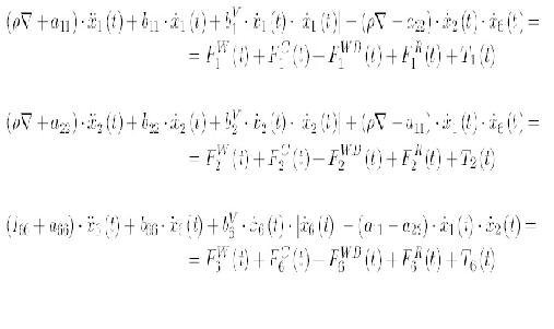
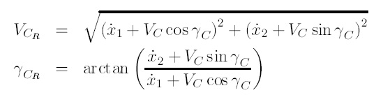
The general form of three nonlinear coupled (Euler) equations of motion in the horizontal plane of the waves, rocking and yaw of the vessel with a dynamic
positioning - with the axes of the system is determined by the formula:
Relative water velocity and direction:
Optimal assessment
Before designing the control system of dynamic positioning is necessary to calculate the noise assessment states. usually this done by applying the estimated aggregate state Kalman and marked Xl, Xh, Xc1, Xw.
Methods for determining the coordinates of the object
Psevdodalnomerny method.
Essence psevdodalnomernogo method is to determine the distances between the navigation satellites, and consumer and the subsequent calculation of the coordinates
consumer. To calculate the coordinates of the three consumer psevdodalnomernym method is necessary to know the distance between the consumer and at least three
navigation satellites. These distances are measured between the phase centers of the transmitting antenna and a satellite navigation receiver antenna of the consumer.
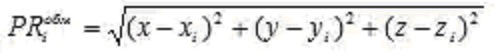
The measured distance between the i-th navigation satellite and the user is called the pseudorange to the i-th satellite. Pseudorange, in general, also
is a calculated value and is calculated as the product of the velocity of propagation of electromagnetic waves and the time during which the signal
satellite's track "satellite - the consumer" will reach the consumer. This time is measured in the apparatus. The measured pseudorange to the i-th navigation
satellite is given by:
Equation (1) can be written in the coordinates of i-th satellite and the coordinates of the consumer as follows:
The differential method.
The differential method for determining the coordinates used to improve the accuracy of navigation determinations performed in consumer equipment. At the heart of
differential method is based on knowledge of the origin or reference point of reference points, which can be calculated by an amendment to the definition
pseudorange navigation satellites. If these amendments into account in consumer equipment, the accuracy of the calculation, in particular, the coordinates can be
increased tenfold.
The equipment, part of the ground augmentation consists of control and correction stations, VHF data link in accordance
in Figure 5. Onboard navigation GNSS receiver and VHF radio signals installed on board a moving object[4,5].
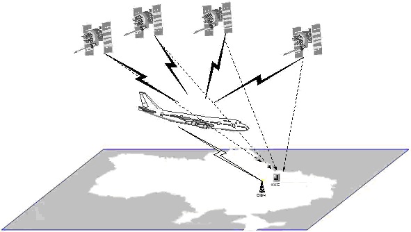
The difference between the calculated and measured pseudorange correction is appropriate pseudo-satellite navigation. Accounting for hardware consumer of that difference and to improve the accuracy of the navigation definitions. In practical systems, the user is transmitted rate of change pseudorange corrections, the application which calculates the corrected pseudorange.
Conclusion
Completed studies, which described the work permit to solve the urgent task of forming a mathematical model
vessel equipped with PAN, in the early stages of the research design. The most significant results include the following work[6]:
1. Analytical description of the aerodynamic characteristics of hydro boat.
2. Model unchanged part of the management system dynamically positioned vessel, that allows you to:
- Provide verification of the validity of prior decision;
- Foster the necessary database to automate the design and the accumulation of personal experience of the designer;
- Serve as the basis for the development of a software automation system design research SDP;
- Improve the process of developing the SDP, reduce labor costs and time to design;
- Improve the efficiency model developed by.
3. The main control algorithm for dynamic positioning, which determines the basic computational operations computing device.
4. Functionally, the SDP concept, which defines the necessary functional elements of the system and the nature of relationships between them.
5. Specifications of measuring subsystem SDP, in general, and gauges, in particular, that determine the composition and structure of the functional diagram measurement subsystem.
6. Method of forming a mathematical model of the unchanging control dynamically positioned vessel at the stage of the research design.
With the developed techniques performed simulations of the vessel, equipped with the SDP. The simulation results confirmed the almost fidelity methods. Completed studies have convincingly shown a real opportunity to create a mathematical model of a ship equipped with PAN, in conditions of incomplete and inaccurate information when the object of management really does not exist, and information about the system is minimal[7].
Remark
Master`s final work is not completed at the moment of writing esse. Date of final completion of work: December 1, 2011. Full text of the work and materials on the topic of work can be obtained from the author or his scientific adviser after that date.
References
-
Structure and working principles of dynamic positioning systems
Source:http://vestnik.mstu.edu.ru/v12_2_n35/articles/12_barak.pdf
-
"Offshore hydromechanics", First Edition. J.M.J. Journee and W.W. Massie. Delft University of Technology. 2001y.;
-
"Guidance and Control of Ocean Vehicles", Fossen Thor I., 1994.
-
Lecture Notes:TTK4190 Guidance and Control, Ivar Ihle, NUST, Norway, 2006;
-
"Marine Control Systems", Fossen Thor I., 2002.
-
Petrov Y., Chervyakov V. Stabilization system drill ships. L., Shipbuilding, 216 s., 1985.
-
Gofman A. Propulsion and maneuverability: A Handbook. L., Shipbuilding,360 с., 1988.